The role of industrial mapping in oil and gas projects
Industrial drawing is one of the main foundations in the implementation of large oil, gas, and petrochemical projects. In these projects, where accuracy and safety are of great importance, having accurate and standardized drawings plays a key role in improving the quality of execution, reducing costs, and preventing human errors.
What is industrial mapping?
Industrial drawing is the process of designing, documenting, and displaying equipment, pipelines, structures, and operational details. These drawings are the common language of all project teams, and proper execution of operations is not possible without them.
The importance of industrial mapping in the oil and gas industry
In oil and gas projects, the volume of equipment and the complexity of systems are very high. In these conditions, industrial drawing helps all parts of the project to be coordinated and executable.
1. Avoiding errors and rework
Accurate drawings make contractors and project executors know exactly what to do.
This prevents additional costs, human errors and project delays.
2. Establishing coordination between different project units
Units such as mechanical, electrical, instrumentation, piping, civil and process must proceed in a specific direction. Drawings ensure complete coordination between all these units.
3. Equipment and process documentation
All technical information, drawings and equipment specifications must be recorded and maintained in accordance with international standards such as API, ASME and ASTM. Industrial drawing is the main basis for this documentation.
Types of maps used in the oil and gas industry
In oil and gas projects, various maps are produced, each of which has a specific role in design and implementation.
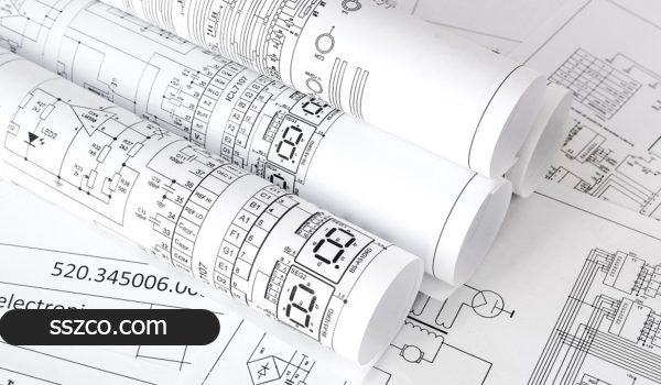
1. Piping Drawings
Piping drawings include the route of pipes, types of lines, fittings, valves and supports. These drawings include the following:
Isometric Drawings
Piping Plan Drawings
Piping Layout Drawings
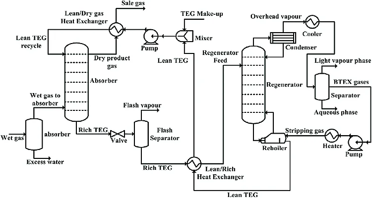
2. Process Drawings (P&ID)
P&ID drawings are one of the most important project documents and show the overall process of the unit, equipment, fluid paths, instrumentation and controls.
3. Mechanical and Structural Drawings
Used for heavy equipment such as tanks, towers, pumps as well as supporting structures.
4. Electrical and Instrumentation Drawings
Used to specify the route of cables, electrical panels, sensors and control systems.
The role of software in industrial mapping
In large oil and gas projects, industrial mapping cannot be done without specialized software. Some of the most useful software are:
Software used
AutoCAD for 2D designs
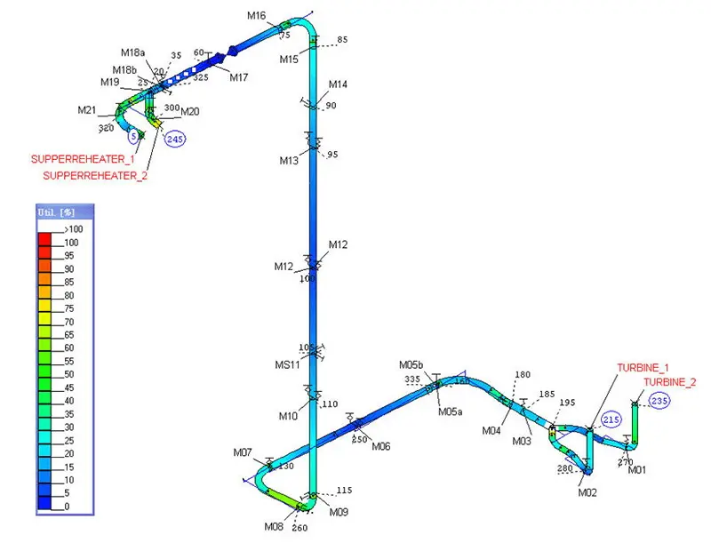
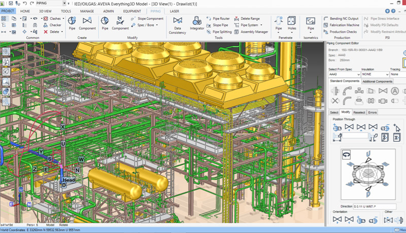
PDMS / E3D for 3D piping modeling
SP3D for advanced piping design
SolidWorks for mechanical parts design
These softwares allow for clash detection, accurate equipment modeling, and reduced execution errors.
Benefits of Accurate Mapping in Oil and Gas Projects
1. Reduce Implementation Costs
Accurate maps reduce material consumption, eliminate rework, and prevent costly mistakes.
2. Increase Speed of Implementation
When implementation teams have all the necessary information in advance, project implementation is much faster.
3. Increase Project Safety
The existence of standard maps reduces the likelihood of accidents and human errors during implementation.
4. Predict problems before implementation
Using 3D modeling, potential problems are identified and corrected before actual implementation.
Conclusion
Industrial mapping is one of the most critical steps in oil and gas projects. The quality and accuracy of these maps have a direct impact on the cost, time, safety, and quality of the project.
In today’s world, where projects have become much more complex, the use of standard maps and professional software is one of the keys to success in implementing oil and gas projects.